Hardware
Hardware Attacks
1.Introduction to Hardware Pentesting: Overview of hardware security, tools and techniques for hardware pentesting, and common attack vectors.
Wireshark: A network packet analyzer that can be used to capture and analyze network traffic.
OpenOCD: An on-chip debugger that supports JTAG and other hardware debugging interfaces.
Bus Pirate: An open-source hardware tool that can be used for debugging and programming embedded systems.
2.Reverse Engineering: Techniques for analyzing hardware and firmware, including JTAG debugging, logic analyzers, and firmware extraction.
Ghidra: A reverse engineering tool that can be used to analyze firmware and software.
binwalk: A tool for analyzing firmware images and extracting embedded files.
J-Link: A JTAG debugging tool that can be used for firmware extraction and debugging.
3.Exploiting Embedded Systems: Techniques for finding and exploiting vulnerabilities in embedded systems, including buffer overflows, format string vulnerabilities, and integer overflows.
GDB: A debugger that can be used to find and exploit vulnerabilities in software.
AFL: A fuzzing tool that can be used to find vulnerabilities in software.
IDA Pro: A disassembler and debugger that can be used for vulnerability analysis.
4.Attacking Cryptography: Techniques for attacking cryptography in hardware, including side-channel attacks, fault injection, and power analysis.
ChipWhisperer: A tool for side-channel analysis and fault injection attacks.
Riscure Inspector: A tool for analyzing and testing the security of embedded systems.
Proxmark: A tool for testing and attacking RFID systems.
5.Exploiting Wireless Interfaces: Techniques for attacking wireless interfaces in hardware, including Bluetooth, Wi-Fi, and RFID.
Aircrack-ng: A tool for cracking Wi-Fi passwords.
Bettercap: A tool for intercepting and manipulating network traffic.
Bluefruit LE Sniffer: A tool for analyzing Bluetooth traffic.
6.Secure Design Principles: Best practices for designing secure hardware, including secure boot, firmware validation, and hardware-based cryptography.
OpenSSL: A library for implementing secure cryptography in software.
YubiKey: A hardware security token that can be used for authentication and encryption.
TOTP: A time-based one-time password algorithm that can be used for two-factor authentication.
7.Testing and Validation: Techniques for testing and validating hardware security, including fuzzing, code review, and penetration testing.
USBKill: A tool for testing the security of USB devices.
Wireguard: A secure VPN that can be used for network security testing.
Nessus: A vulnerability scanner that can be used for penetration testing.
Car Hacking
1.Understanding Automotive Architecture:
Learn the different components of the modern automobile, such as the Engine Control Unit (ECU), Controller Area Network (CAN) bus, and OBD-II port.
Understand the protocols and data formats used by different automotive systems, including CAN, LIN, FlexRay, and Ethernet.
Study the hardware and software tools used for automotive hacking, such as JTAG debuggers, logic analyzers, and reverse engineering tools.
2.Exploiting Onboard Diagnostic Systems:
Use a scan tool or OBD-II dongle to read and interpret data from the OBD-II port.
Explore the different OBD-II modes and commands to gather information and control vehicle functions.
Use tools like CANtact or SocketCAN to interact with the CAN bus and send custom messages to control vehicle systems.
3.Reverse Engineering ECU Firmware:
Use tools like IDA Pro or Ghidra to disassemble and analyze ECU firmware.
Understand the architecture and instruction set of the ECU processor, such as ARM or PowerPC.
Look for vulnerabilities in the firmware, such as buffer overflows, memory leaks, and backdoors.
4.Attacking Wireless and Cellular Interfaces:
Study the different wireless protocols used in modern vehicles, such as Bluetooth, Wi-Fi, and Cellular.
Use tools like Ubertooth or Bluefruit to sniff and inject Bluetooth traffic.
Use tools like OpenBTS or Osmocom to set up a cellular base station and intercept cellular traffic.
5.Hacking Vehicle Networks:
Use tools like CANBus Triple or CANalyzerto sniff and inject CAN bus traffic.
Study the different network topologies used in vehicles, such as star, bus, and ring.
Understand the vulnerabilities of each network topology, such as spoofing, injection, and DoS attacks.
6.Exploring Connected Car Infotainment Systems:
Understand the architecture and components of modern infotainment systems, such as Android Auto and Apple CarPlay.
Use tools like ADB or Xposed to modify and customize infotainment systems.
Look for vulnerabilities in infotainment systems, such as SQL injection, buffer overflows, and XSS attacks.
7.Building a Car Hacking Lab:
Set up a dedicated environment for automotive hacking, including hardware and software tools.
Use virtual machines or emulators to simulate vehicle systems and components.
Follow best practices for safety and security, such as using isolation transformers, fuses, and fire extinguishers.
Hardware Toolkit
DIY
BadUSB
Digispark
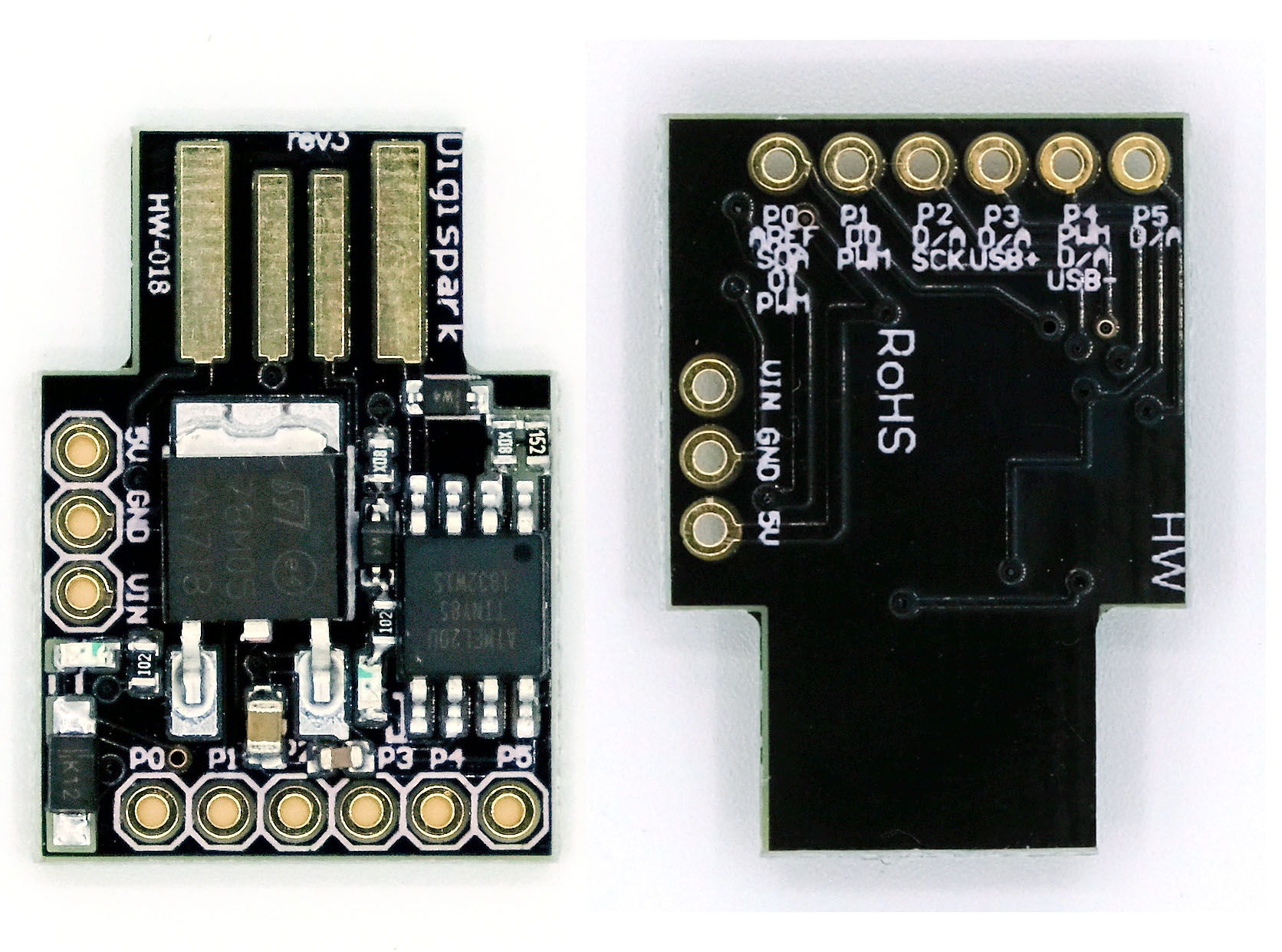
Open the Arduino IDE and select “Digispark (Default - 16.5MHz)” from the “Tools” > “Board” menu.
Write a script that will be executed by the Digispark. This script can be written in the Arduino IDE using the “Sketch” > “New Sketch” menu. Here is an example script that opens the command prompt and types in a series of commands:
Upload the script to the Digispark by clicking the “Upload” button in the Arduino IDE.
Sub-1 GHz Transceiver
HopeRF RFM69HCW
Materials:
Arduino board (UNO or Nano)
Sub-1 GHz transceiver module (such as the HopeRF RFM69HCW)
Antenna
Breadboard
Jumper wires
USB cable
3.7V Li-ion battery
CC1310 or CC1101
The Sub-1 GHz transceiver module can be built using an RF chip such as the CC1310 or CC1101, which are low power consumption chips with a range of up to several kilometers. For programming, you can use languages such as C or Python to control the RF chip.
Here are the steps to build your Sub-1 GHz transceiver:
Start by selecting the RF chip that meets your requirements and purchase it along with a development board.
Download the necessary software tools such as Code Composer Studio or IAR Embedded Workbench and set up the development environment.
Connect the development board to your computer and start programming using C or Python.
Follow the datasheet provided with the RF chip to configure the transceiver module with the appropriate settings for your application.
Test the module by sending and receiving data between two transceivers.
Once the module is tested and verified, you can integrate it into your project.
125kHz RFID
Materials:
Arduino Uno or compatible board
MFRC522 RFID reader module
RFID tags/cards
Breadboard
Jumper wires
Circuit Diagram:
Connect the RFID reader module to the Arduino board using jumper wires. The connections are as follows:
RFID module SDA pin to Arduino digital pin 10
RFID module SCK pin to Arduino digital pin 13
RFID module MOSI pin to Arduino digital pin 11
RFID module MISO pin to Arduino digital pin 12
RFID module VCC pin to Arduino 5V pin
RFID module GND pin to Arduino GND pin
Connect the RFID tag antenna to the RFID reader module. The antenna can either be a coil of wire or an actual RFID tag.
Upload the RFID library to the Arduino board. You can find the library and instructions on how to install it on the Arduino website.
Write the code to read the RFID tag data. Here is an example code that will read the tag data and display it on the serial monitor:
Test the system by holding an RFID tag near the reader antenna. The tag data should be displayed on the serial monitor.
NFC
PN532
Materials:
Arduino Uno or compatible board
PN532 NFC/RFID reader and writer module
Breadboard
Jumper wires
USB cable
Here are the steps to create an NFC reader and writer with Arduino:
Step 1: Connect the PN532 NFC/RFID module to the Arduino board.
Connect the PN532 module to the Arduino board using the following pins:
VCC to 5V
GND to GND
SDA to Digital Pin 10
SCK to Digital Pin 13
MOSI to Digital Pin 11
MISO to Digital Pin 12
IRQ to Digital Pin 2
Step 2: Connect the Arduino board to your computer.
Connect the Arduino board to your computer using the USB cable.
Step 3: Install the necessary libraries.
You will need to install the Adafruit PN532 library to interface with the PN532 module. Open the Arduino IDE, go to Sketch > Include Library > Manage Libraries, search for “PN532” and install the Adafruit PN532 library.
Step 4: Upload the code to the Arduino board.
Copy and paste the following code into the Arduino IDE:
This code sets up the PN532 module as an NFC reader and prints the UID of any detected NFC tag.
Upload the code to the Arduino board by clicking on the Upload button.
Step 5: Test the NFC reader.
Open the Serial Monitor in the Arduino IDE and hold an NFC tag near the PN532 module. The UID of the tag should be printed in the Serial Monitor.
Step 6: Write data to an NFC tag.
To write data to an NFC tag, you will need to modify the code from Step 4. Here is an example code that writes a text message to an NFC tag:
Infrared Transmitter
TSOP38238
Get an Arduino board and an IR receiver module, such as the TSOP38238. The datasheet for the TSOP38238 can be found online, which provides detailed information on how to connect the module to an Arduino board and how to read IR signals.
Connect the IR receiver module to your Arduino board, following the pinout provided in the datasheet.
Download and install the IRremote library for Arduino, which provides a convenient interface for working with IR signals.
Use the IRremote library to read incoming IR signals from a remote control. You can use the example code provided with the library as a starting point and modify it to fit your needs.
Once you have successfully read IR signals from a remote control, you can use this information to control other devices that use IR signals, such as TVs, DVD players, and air conditioners.
This code sets up an IR receiver module connected to pin 11 of the Arduino board. The code uses the IRremote library to receive and decode incoming IR signals from a remote control. The decoded signal is printed to the serial monitor in hexadecimal format.
Product
Flipper Zero
Swiss Army Knife
Raspberry Pi 3 model B+
Multi-attack tool Linux based board
ODROID XU4
Fully energized Raspberry Pi
Cubox-i2ex
Multi-attack tool Linux based board
RTL-SDR v.3
Cheap and powerful SDR RX device
Flamingo FM
Broadcast FM Bandstop Filter for SDR
HackRF One
Medium-category SDR with TX capabilities
Crazyradio PA
USB 2.4GHz transceiver
nRF52840 USB Dongle
USB 2.4GHz transceiver next generation
Yardstick
Sub 1GHz radio stick
Ubertooth One
The best Bluetooth hacking device
APImote v.4b
Hacking Zigbee IoT protocol
RF power meter
Measuring RF output power
BladeRF xA4
High RF quality SDR device
Alfa AW-US036NHA
The best 2.4 GHz Wi-Fi 802.11n device
Alfa AWUS-036ACH
The best 2.4 / 5 GHz Wi-Fi 802.11ac device
4 Watt 2.4 GHz amplifier
Wi-Fi / Bluetooth booster
2.4 GHz/9 dBi omni antenna
A good solution to upgrade your horizons
2.4GHz/15dBi yagi antenna
If you need to get far away, you need it
Wi-Fi deauther
The best 2.4 GHz Wi-Fi 802.11n device
Proxmark3-EVO
Latest and most powerful NFC device
NFCKill
RFID destruction device
SCM SCL3711
RFID miniature 13.56MHz reader/writer
HydraNFC
Sniffer / reader / writer/ emulator for HF
ACR-122U
13.56MHz RFID/NFC reader/writer
WHID injector
USB rubberducky on steroids
Badusb Wi-Fi microSD
The most complete Rubberducky
Badusb microSD
Badusb with SD card for your payloads
USBNinja
Wireless BadUSB / Rubberducky
Digispark Kickstarter mini
Cheap and fully-working Rubberducky
AirDrive Keylogger Max
One of the most advanced keyloggers
Gl-Inet AR150
OpenWRT/LEDE router Pinapple
USB to miniPCIe adapter
Modem adapter with SIM socket
Gl-Inet USB150 Minirouter
OpenWRT/LEDE based router devices
Logic pirate
Logic analyser for complicated signals
The Shikra
Bus pirate JTAG big brother
DIVA IoT board
Damn Insecure and Vulnerable Application
USB to TTL/UART
Last and most powerful NF device
STM32 programmer/debugger
Programming/debugging for STM32 micros
AVR programmer/debugger
Programmer/debugger for ATmega micros
USB Infrared Toy v2
Bus pirate JTAG big brother
USB power monitor
Monitors and logs USB power details
USB Kill v3
System destroyer device
USB condom
The original USB condom
iFixit Opening Toolkit
The essential tool to open every new toy
Lockpicking training kit
Real hackers know lockpicking
Last updated